Mahmote
A development platform for IoT applications.
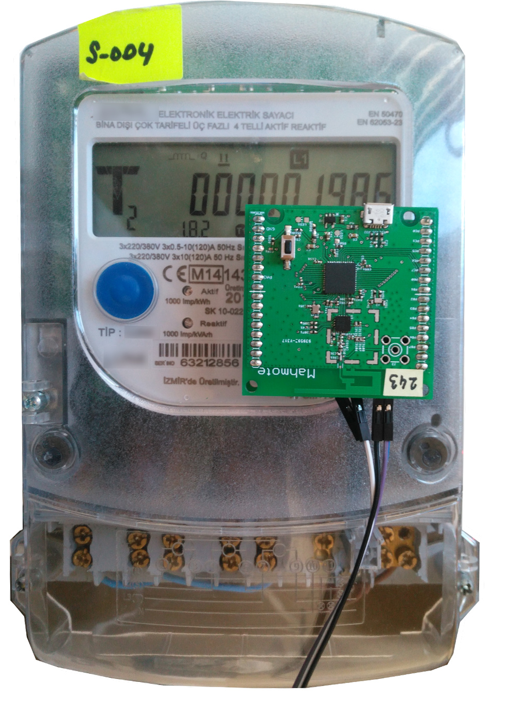
This platform intended as a development and test platform for IoT specific software implementations. The hardware is designed for ease of use where the developed software can easily be uploaded on to the hardware via the USB interface on the base board as it is seen from Fig. 1. The binary firmware files are sent to the platform through the base board and the same board can be used for debugging the hardware via the USB serial port. The target SoC can be programmed by pressing down the push button located on the base board which puts cc2538 SoC to backdoor mode. This lets the host computer to download the binary firmware to the EPROM of the SoC.
The base board comes with two ports which can be used to collect temperature and ambient light information digitally using Analog to Digital Converters (ADC) of cc2538 SoC. The base board also have a JTAG header which can be used to program the cc2538 SoC using xds100v3 JTAG emulator. The USB base board can support data rates of up to 1Mbit/second. Furthermore, it can be used to create a network interface to a host computer via SLIP (Serial Line IP) protocol to allow configuration of the cc2538 SoC as an edge router.
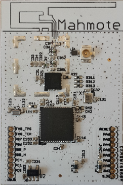
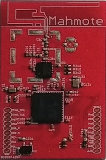
Fig. 1: Mote Platform and Base Board
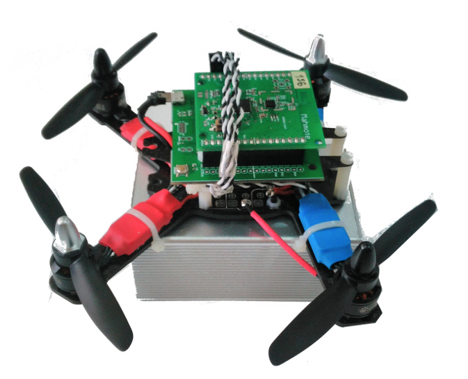
The mote platform consists of a cc2538 SoC and a range extender(cc2592). A specification summary of the SoC is given in Table I. The SoC supports many low power applications with a PHY that is compatible with IEEE 802.15.4-2006 specifications. It has many useful features such as hardware accelerators for security and ADCs. SoC can have a maximum transmit power of 7 dBm and it has a receiver sensitivity of -97 dBm. Furthermore, it supports different power modes with RAM retention for low power operation. When used with cc2592 the mote can output a maximum of 20 dBm and receiver sensitivity reaches aroud -102 dBm which enables the devices to support longer ranges. The platform tests revealed that a range of 300 meters is achievable in an NLOS outdoor environments. Furthermore, indoor office tests also revealed a communications range of 100 meters.
The
platform tested for Contiki embedded OS and has been provided with
necessary Contiki software drivers to use the cc2592 LNA chip and the
ambient light and temperature sensors. The radio can be programmed to
support different different power modes which can be used to support
dynamic power control. The cc2592 LNA can be also programmed for
different modes to control its energy budget.
The
board can have two antenna configurations. The board can be
configured to use the on-board Planar Inverted F Antenna (PIFA) by
soldering C37 capacitor to the PIFA connection. Furthermore, an
external antenna can be used with the board by soldering C37
capacitor to the SMA connector which may be used to attach a high
gain antenna to the board for extended range.
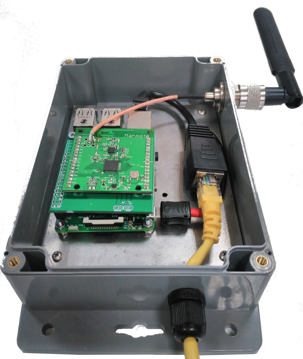
The
mote has 24 general purpose I/O connections attached to two standard
connectors which can be used to connect the device to the sensors and
actuators as necessary. 4 I/O pins can support currents of 20 mA
which can be used to power up low power sensors and power them down
when they are no longer used. This enables low energy consumption
configuration enabling long life time for battery based operations.
Table I : CC2538 Specification Summary
Microcontroller
- Powerful ARM ® Cortex®-M3 With Code Prefetch.
- Up to 32-MHz Clock Speed.
- 512KB, 256KB or 128KB of In-System-
Programmable Flash. - Supports On-Chip Over-the-Air Upgrade (OTA).
- Supports Dual ZigBee Application Profiles
- Up to 32KB of RAM (16KB With Retention in All Power Modes)
- cJTAG and JTAG Debugging
RF
- 2.4-GHz IEEE 802.15.4 Compliant RF Transceiver.
- Excellent Receiver Sensitivity of –97 dBm.
- Robustness to Interference With ACR of 44 dB.
- Programmable Output Power up to 7 dBm.
Security Hardware Acceleration
- Future Proof AES-128/256, SHA2 Hardware Encryption Engine.
- Optional – ECC-128/256, RSA Hardware Acceleration Engine for Secure Key Exchange.
- Radio Command Strobe Processor and Packet Handling Processor for Low-Level MAC Functionality
Low Power
- Active-Mode RX (CPU Idle): 20 mA
- Active-Mode TX at 0 dBm (CPU Idle): 24 mA
- Power Mode 1 (4-µs Wake-Up, 32-KB RAM
Retention, Full Register Retention): 0.6 mA - Power Mode 2 (Sleep Timer Running, 16-KB
RAM Retention, Configuration Register
Retention): 1.3 µA - Power Mode 3 (External Interrupts, 16-KB
RAM Retention, Configuration Register
Retention): 0.4 µA - Wide Supply-Voltage Range (2 V to 3.6 V)
Peripherals
- µDMA
- 4 × General-Purpose Timers
(Each 32-Bit or 2 × 16-Bit) - 32-Bit 32-kHz Sleep Timer
- 12-Bit ADC With 8 Channels and Configurable
Resolution - Battery Monitor and Temperature Sensor
- USB 2.0 Full-Speed Device (12 Mbps)
- 2 × SPI
- 2 × UART
- I2C
- 32 General-Purpose I/O Pins
(28 × 4 mA, 4 × 20 mA) - Watchdog Timer